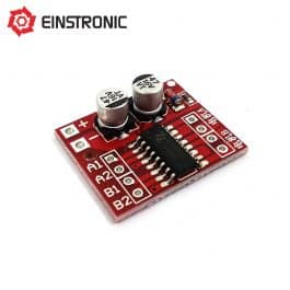
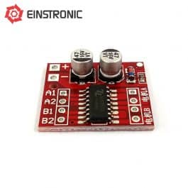
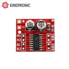
DRV8833 Motor Driver Module
RM5.00
7 in stock
Description
This is compact, small module designed to be used with small mobile robots. It can control 2 brushed DC motors or 1 bipolar stepper motor.
Features
- Motor voltage : 2.7 – 10.8 V
- Logic voltage : 3 – 5 V
- Max. output current : 2 A (per H-bridge)
- Continuous output current : 1.5 A
Wiring
| Label | Meaning | Connection |
| IN3, IN4 | Direction control B | Connect to digital pin of Arduino |
| GND | Ground | Connect to GND of system |
| VCC | Motor power | Connect to positive terminal of power source |
| IN1, IN2 | Direction control A | Connect to digital pin of Arduino |
| SLEEP | Sleep / Enable pin | Connect to digital pin of Arduino (optional) |
| OUT1, OUT2 | Motor A | Connect to motor A |
| OUT3, OUT4 | Motor B | Connect to motor B |
| FAULT | Fault return pin | Connect to digital pin of Arduino (optional) |
Power source can be either battery, power adapter or Arduino 5V

IN1 and IN2 are direction control pins for motor A, corresponding to OUT1 and OUT2; IN3 and IN4 are direction control pins for motor B, corresponding to OUT3 and OUT4.
Two inputs are directly corresponding to the respective output, work as described in the truth table below
| IN1 | IN2 | OUT1 | OUT2 | Motor state |
| LOW | LOW | LOW | LOW | Coasting |
| LOW | HIGH | LOW | HIGH | Forward / Backward |
| HIGH | LOW | HIGH | LOW | Backward / Forward |
| HIGH | HIGH | HIGH | HIGH | Braking |
** This is just an example of response from the module, please verify with your motor response for the input signals **
Note : The Ground of the module must be shared common to both negative terminal of battery and the GND of Arduino in order for the signals to work properly.
Working Principle of this module is same as L298N Motor Driver Module.
Attachments
** This module comes with unsoldered header pins, kindly reach us if you need soldering help **
Additional information
| Weight | 2 g |
|---|---|
| Dimensions | 19 × 15 × 10 mm |